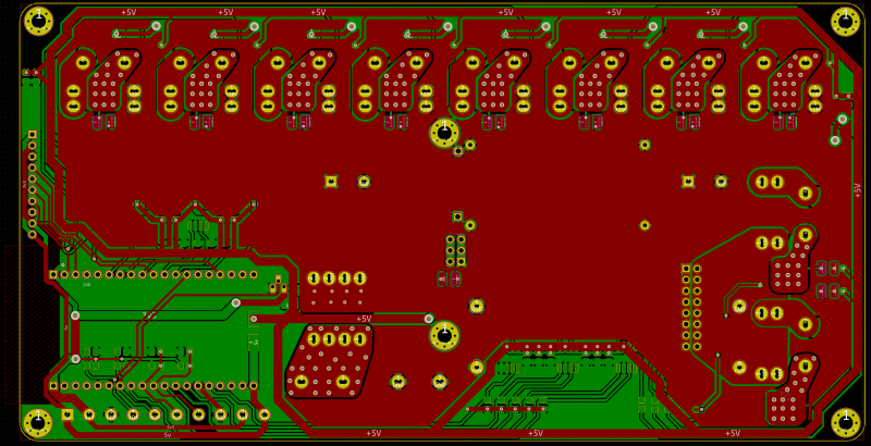
QuinLED-Deca-Plus Hardware guide
I’ve decided to slightly redesign this project (mostly PCB, not components), hoping for completion somewhere Q3-Q4 2020
For information about the different revisions, please see the QuinLED-Deca-Plus Revision history
If you are looking for information about the board and it’s capabilities, please take a look over here first
To build the QuinLED-Deca-Plus you are going to need several components which are listed below. As a little disclaimer, please take a look at this article about my shopping links. After reading that, make sure to also take a look at the additional hardware and tools you might need to be able to complete this project. And last but not least, check out my article about 12v or 24v LED strips and what to watch out for while buying led strip (The color white) and what my favorite strips are! Click here if you are looking for RGB LED strip!
Those articles are a lot of information but will teach you everything you need to know! If you have any questions about the components, let me know in the comments!
[IMAGE OF ALL COMPONENTS LAID OUT]
Total costs for a single board
A single fully built QuinLED-Deca-Plus board will cost a bit more then my other boards, since the size of the board is 200mm x 100mm production cost for 10 PCBs alone is between 50$ and 100$ (depending on options). Adding components (including onboard DC-DC converter for the 2 separate channels, ESP32, terminals, level-shifters, MOSFETs, LEDs, etc.) will cost about you about xx$ in total component cost (buying everything in 100 fold, enough for up to 10 boards). So in total this would cost you xxx$. If you completed those 10 boards the cost per board would be ~xx$.
Partly because of the above scenario being very costly I am looking into making half pre-built and fully pre-built boards available, please read more about that here.
[FINAL BOARD SHOT]
Board Summary
You need the following components and quantities:
Components needed
Since the QuinLED-Deca-Pro uses a lot of components per board (a lot of components are in 10 fold per board) I recommend buying minimum quantities of 50 or even 100 pieces. My links will mostly be toward 100 items of a piece since this is often also the best price per component available, buying in bulk saves money! Also when buying larger amounts of components you slowly but surely amass common components used in hardware tinkering and they are convenient to have lying around!
Not all components can be hand soldered and you will need a hot-air gun or even soldering oven! Please see the following page for equipment and tools you might need to complete this project!
All amounts of the components will be listed in green text. The amount listed there is for building a single board!
![]()
QuinLED-Deca-Plus PCB boards
- 1x QuinLED-Deca-Plus PCB
For ordering the PCB boards you can choose between buying the boards from DirtyPCBs or PCBway. I use both supplier regularly and it really depends on your location and amount of boards you want which is cheaper. Both offer excellent quality so you can’t go wrong there!
Cheap/Slow shipping is SLOW (sometimes 8+ weeks). PCBway e-packet is a good compromise between decent time and money
![]() DirtyPCB QuinLED-Deca-Plus
DirtyPCB QuinLED-Deca-Plus
![]() PCBway QuinLED-Deca-Plus
PCBway QuinLED-Deca-Plus
⭐ If you do not have a PCBway account yet, consider creating one using this affiliate link! 🙂 After creating come back to this page and use order link above.
📚 While ordering, choose 20x10cm (200mm x 100mm) boards, 1.6mm thickness, Copper OZ needed and a color! Rest of the options are correct as default.
Gerber files?
I currently do not have the gerber files available. I might release these in the future so you can use your own favorite board house but in the past I’ve had issues where people would keep using old versions because that’s what they downloaded or was posted on a forum at some point in time. That complicates things such as optimizing and improving or fixing bugs in the design over time. Also, I know DirtyPCB and PCBway can make my design correctly and give me a little kickback if someone places an order there, which helps me again to make and test new revisions, etc.. I hope you can understand.
![]()
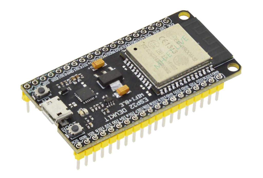
MH-ET-Live ESP32 development board
The main brains of the dimmer is the ESP32. Instead of using the raw modules I opted to use a ready-made development board so that it’s much easier to solder and comes with everything you need such as the USB port and a voltage converter to 3.3v.
*Although different brands/boards can be used, some ESP32 development boards have different pin-outs which will not work!
- 1x MH-ET-Live ESP32 Development board
![]() 1x MH-ET-Live ESP32 development board
1x MH-ET-Live ESP32 development board
![]() 10x MH-ET-Live ESP32 development boards (If you plan on doing multiple boards or other projects, get the 10 pack, they become much cheaper in bulk!)
10x MH-ET-Live ESP32 development boards (If you plan on doing multiple boards or other projects, get the 10 pack, they become much cheaper in bulk!)
Make sure not to NOT connect both a power supply AND USB at the same time!
![]()
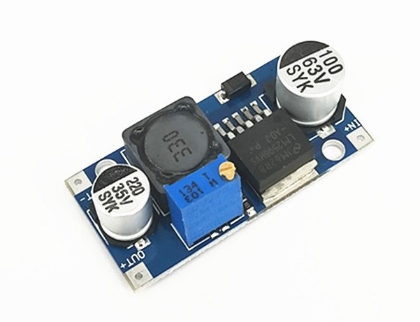
DC-DC Voltage converter for ESP32
The ESP32 and MOSFET Gate Drivers on the QuinLED-Deca-Plus need a stable 5.2v, for this we are going to use a pre-built DC-DC converter board! This board can accept ~6.5v to 40v in.
- 1x DC-DC set to 5.2v
📚 Leave board power enable jumpers off while setting voltage! Once set to 5.2v you can add the 3x Jumpers to enable power to go to the rest of the board!
DC-DC Converter (up to 40v) model
![]() 5x LM2596 max 40v DC-DC converter
5x LM2596 max 40v DC-DC converter
![]()
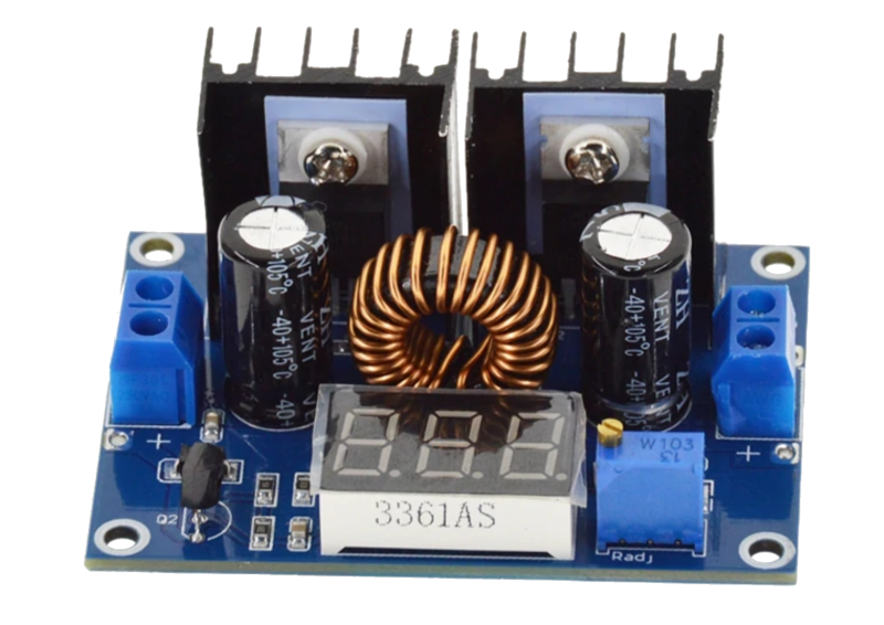
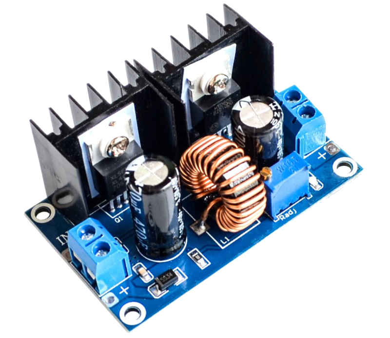
Optional: Big DC-DC Voltage converter for Channel 9 & 10
If you want to be able to set a different (lower then input) voltage on channel 9 & 10 you will need a DC-DC converter for that. There is two models you can choose from, with and without a screen, please see here for more information about this converter. I recommend not exceeding a continuous load of higher then 4A input without active (a fan) cooling.
- 1x Big DC-DC buck converter with or without display
📚 This DC-DC converter is optional, if you want to use the same voltage for channel 9 & 10 it can be left off
Big DC-DC buck converter
![]() Big DC-DC converter with screen
Big DC-DC converter with screen
![]()
Big DC-DC converter without screen
Converter with Screen
Converter without screen
![]()
2.54mm Female Pin Headers
Because we want to use all the available space as efficiently as possible we’re using some female headers to raise up the ESP32 Development board. That also means that if you make a new revision board in the future you can just move the ESP32 module!
- 2x 19 pins 2.54mm female header
- If you can’t source 19 pins headers a 20 pin header can also work (you will need to snip off the last pin to make it fit (only the metal part)
![]() 19 pins 2.54mm Female Header “socket”
19 pins 2.54mm Female Header “socket”
![]()
20 pins 2.54mm Female Header “socket”

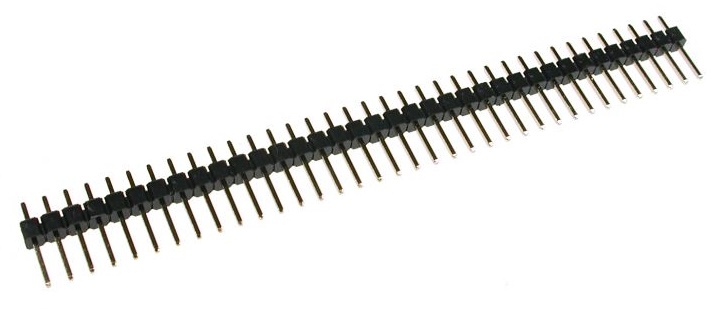
2.54mm Male Pin headers
To mount the DC-DC converters, ESP32 (comes with pins included) and dupont connections for GPIO we need some pins to neatly mount everything. The easiest way to do this is to use simple 2.54 male pin headers.
- 40x 2.54mm Male Pin Headers
- 4x for DC-DC converter 5.2v
- 4x for DC-DC converter channel 9+10
- OR 16x for by-pass channel 9+10
- 6x for power enable headers
- 10x for GPIO headers
![]() 20 pcs 40 pin 2.54mm pin header strip (Silver)
20 pcs 40 pin 2.54mm pin header strip (Silver)
![]() 20 pcs 40 pin 2.54mm pin header strip (Gold)
20 pcs 40 pin 2.54mm pin header strip (Gold)
Jumpers
The QuinLED-Deca-Plus uses jumpers in several spots, you need these to be able to power on the board!
- 11x 2.54mm Jumper
- 3x board power enable jumpers
- 8x Channel 9 & 10 by-pass jumpers
![]()

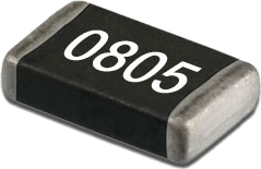
0805 Resistors
To make sure several components function correctly there are several different types of resistors on the board!
*You will need a tweezer to put these into place, make sure to check out the tools section!
Total resistors needed:
- 20x 0805 10k Ohm resistor
- LED dimming channels after ESP32
- LED dimming channels after MOSFET gate drivers
- 1x 0805 4.7k Ohm resistor
- Onboard DS18B20 temperature sensor
- 1x 0805 3.3k Ohm resistor (333)
- Board Power LED
- 10x 0805 430 Ohm resistor (431)
- LED Dimming channels status LEDs
- 10x 0805 10 Ohm resistor
- Current limiting resistor between level-shifter and MOSFET gates
10k Ohm resistors
- 20x 0805 10k Ohm resistor
![]() 100 Pcs 0805 resistor (Has all values to choose from)
100 Pcs 0805 resistor (Has all values to choose from)
4.7k Ohm resistors
- 1x 0805 4.7k Ohm resistor
![]() 100 Pcs 0805 resistor (Has all values to choose from)
100 Pcs 0805 resistor (Has all values to choose from)
3.3k Ohm resistors
- 1x 0805 3.3k Ohm resistor
![]() 100 Pcs 0805 resistor (Has all values to choose from)
100 Pcs 0805 resistor (Has all values to choose from)
430 Ohm resistors
Used for the per dimming channel status LED
- 10x 0805 430 Ohm resistor
![]() 100 Pcs 0805 resistor (Has all values to choose from)
100 Pcs 0805 resistor (Has all values to choose from)
10 Ohm resistors
Used for the per dimming channel status LED
- 10x 0805 10 Ohm resistor
![]() 100 Pcs 0805 resistor (Has all values to choose from)
100 Pcs 0805 resistor (Has all values to choose from)
Another option (for 1 to 2 boards total)
Instead of buying all values individually you can also buy a 0805 resistor sample book. These have lots of resistors types included and mostly carry at least 20pcs per value!
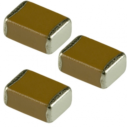
0805 Capacitors
Since the QuinLED-Deca-Plus is a lot bigger and handles a lot more power we’re going to need a few capacitors to keep everything stable under all conditions!
- 9x 0805 0.1 uF/100 nF Capacitor
- 6x for MOSFET drivers
- 2x for LED power
- 1x for DS18B20 Temperature Sensor
- 6x 0805 1 uF Capacitor
- 6x for MOSFET drivers
- 2x 0805 10.0 uF Capacitor
- 2x LED power
*You will need a tweezer to put these into place, make sure to check out the tools section!
![]() 100 Pcs 0805 0.1 uF/100 nF Capacitor
100 Pcs 0805 0.1 uF/100 nF Capacitor
Another option (for 1 to 2 boards total)
Instead of buying all values individually you can also buy a 0805 capacitor sample book. These have lots of capacitors types included and mostly carry at least 20pcs per value!
Optional: 1206 SMD LEDs
I decided to include a board power status LED and an LED per channel which will light up with the same value as the channel is currently dimmed to. That means that even if your lights are in a different room then the controller board you will still be able to tell roughly what power level that channel is set to! These LEDs are optional, colors and intensity can also be chosen freely! Keep them 2106 size and maybe change the corresponding resistor depending how bright you want them to be. Below are the examples I am using after testing several different combinations!
📚 The 2106 SMD LED diodes have have polarity, match up green side with dot on PCB!
- 1x 1206 SMD Green LED
- Board power status LED
- 10x 1206 SMD Amber/Yellow LED
- One for each channel
*You will need a tweezer to put these into place, make sure to check out the tools section!
![]()
Seller page or Assortment of 2106 SMD LEDs
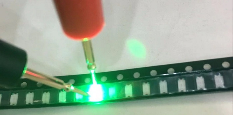
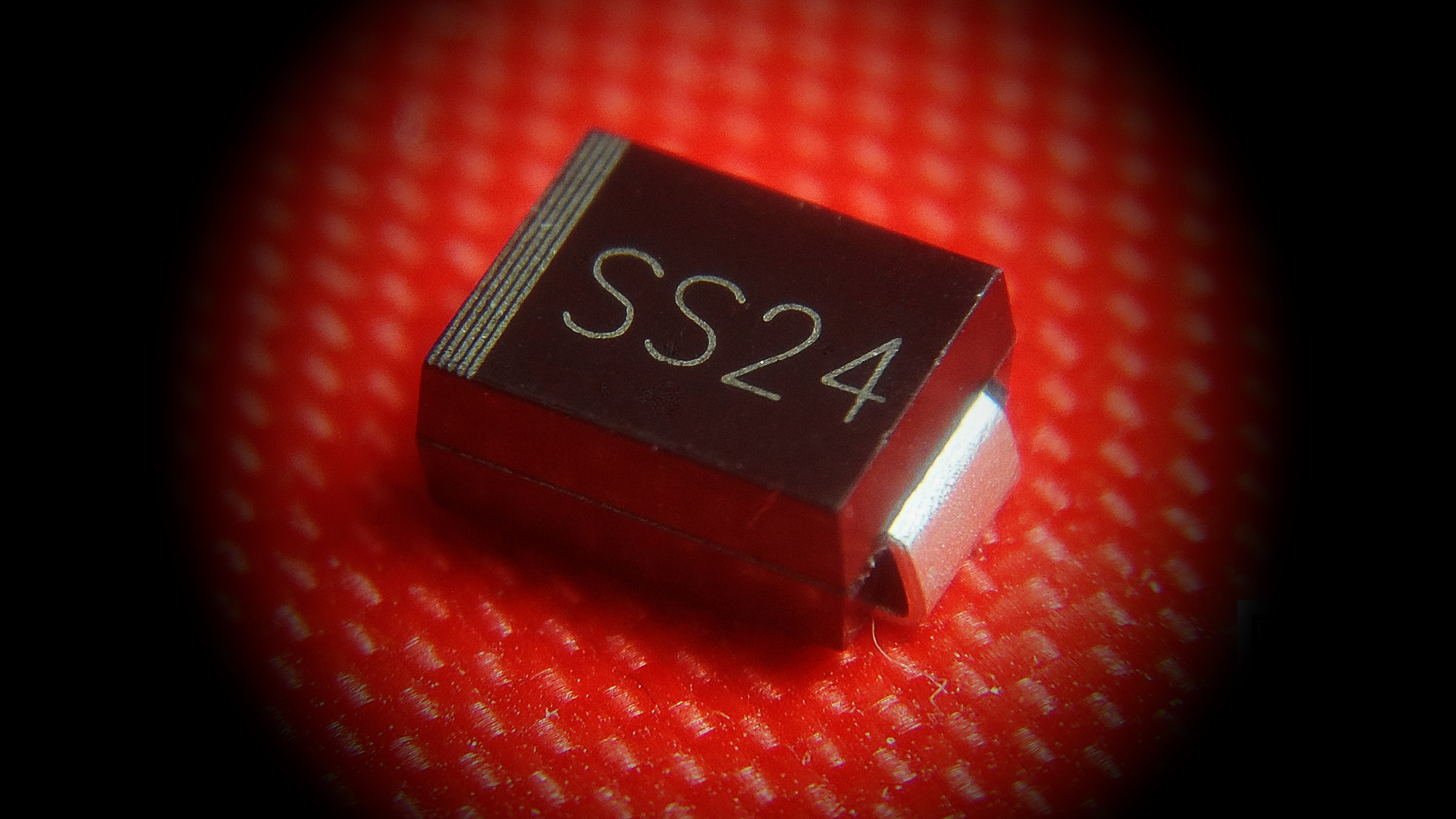
SMD SS24 Diode
Lots of diodes are used on the QuinLED-Deca-Plus to try and safeguard the board and connected items!
📚 The SS24 diodes have polarity, match up stripes with the stripes on the PCB!
- 13x SS24 Diode
- 1x for ESP32 input
- 2x for Board Power input
- 10x for LED dimming channels
*You will need a tweezer to put these into place, make sure to check out the tools section!
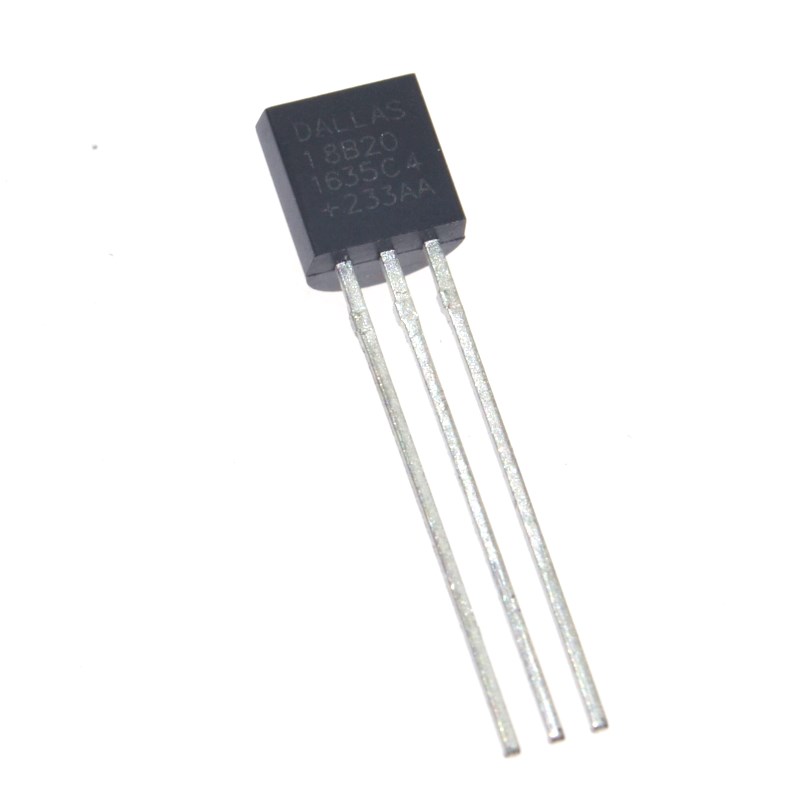
Optional: Dallas DS18B20 TO-92 Temperature sensor
All the boards, including the QuinLED-Deca-Plus have a spot for a Dallas DS18B20 TO-92 temperature sensor. It’s a cheap way to add a little sensor to the board!
⭐ The board has a screw terminal to which you can hook up extra wired Dallas one-wire sensors (they form a bus) if you wish to read external temperatures such as the room, very easily! (use 3.3v power)
- 1x Dallas DS18B20 TO-92 temperature sensor
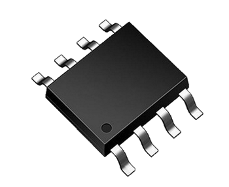
SMD TC4427A MOSFET Gate Driver
Although we are using the same MOSFETs as on the QuinLED-Quad to enable a (much) higher power output efficiently we are driving the GPIO pins MOSFET gate driver, uplifting the signal from 3.3v to 5.2v to “bang open” the MOSFETs extra hard. Because of this there is less heat build-up and an output of 8A per MOSFET can be achieved (combined with a much larger heat-sink area on the PCB). It also seems to enable somewhat more granular control in the bottom regions of the dimming slider!
❗These are harder to solder by hand then the other components, best is to use a hot-air soldering station & paste or soldering oven❗
- 6x TC4427A MOSFET Gate Driver (SOP-8)
![]() 20 Pcs TC4427A MOSFET Gate Driver IC
20 Pcs TC4427A MOSFET Gate Driver IC
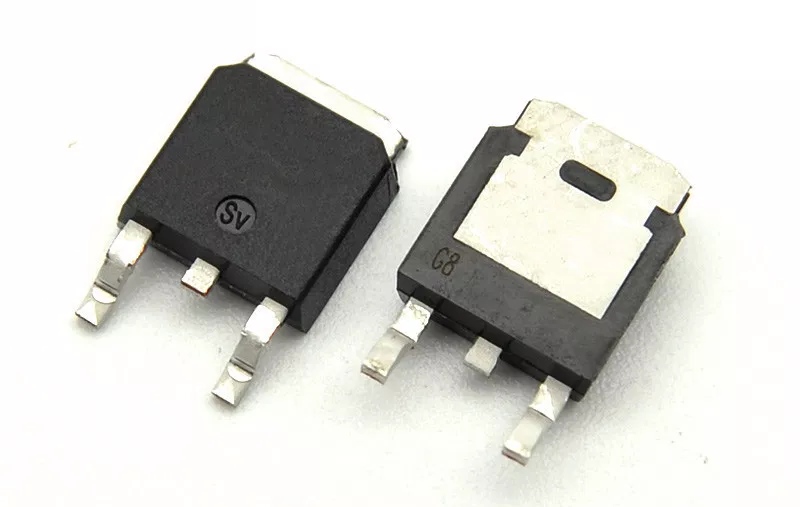
LED dimming MOSFETs
To switch the high current LEDs with the low power of the ESP32 we need some MOSFETs. On the QuinLED-Deca-Plus we use TO-252 size MOFSETs.
I have tested three variants of these, the FDD8447L , the LR3636 and the LR2905 and all work fine. I generally use the FDD8447L because it has the best properties, I’ve never had a bad batch and it’s often the cheapest too.
- 10x TO-252 MOSFET
❗These are harder to solder by hand then the other components, best is to use a hot-air soldering station & paste or soldering oven❗
FDD8447L
![]() 100 pcs FDD8447L TO-252 MOSFET
100 pcs FDD8447L TO-252 MOSFET
LR3636
![]() LR3636 TO-252 MOSFET (Aliexpress only) (Slightly better choice if running voltage close to 40v)
LR3636 TO-252 MOSFET (Aliexpress only) (Slightly better choice if running voltage close to 40v)
LR2905
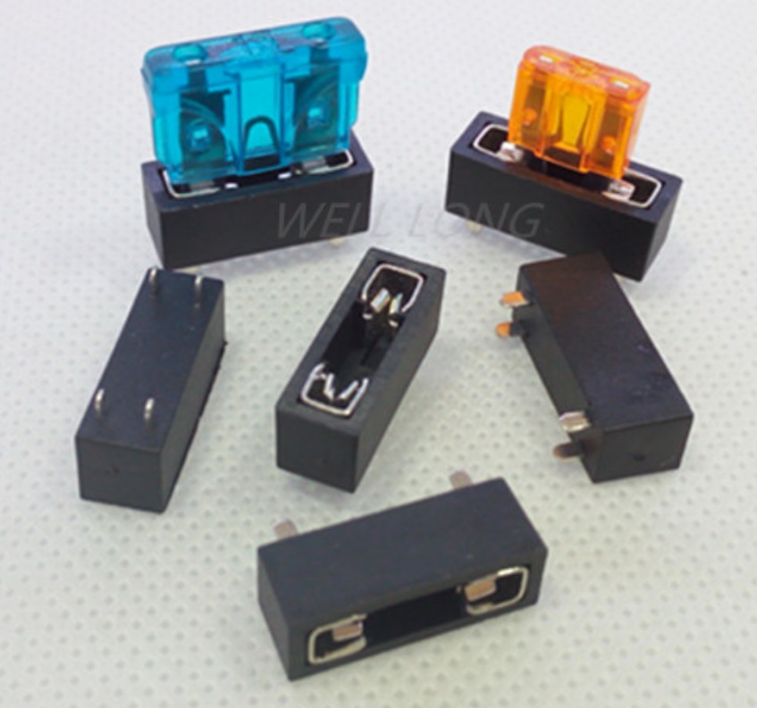
PCB Fuse holder
The QuinLED-Deca-Plus features dual input fuses (in a load-sharing setup) and has 10x output channel fuse. Please see maximum power usage recommendations for the board here!
- 12x PCB fuse holder
- 2x main input power
- 10x output channel
![]()
![]()
📚 Shipping can take very long with the default shipping method, choose “Aliexpress standard shipping” as minimum!
📚 You can also find them on Mouser or otherwise maybe Ebay. Try searching for part nr: 3557-2
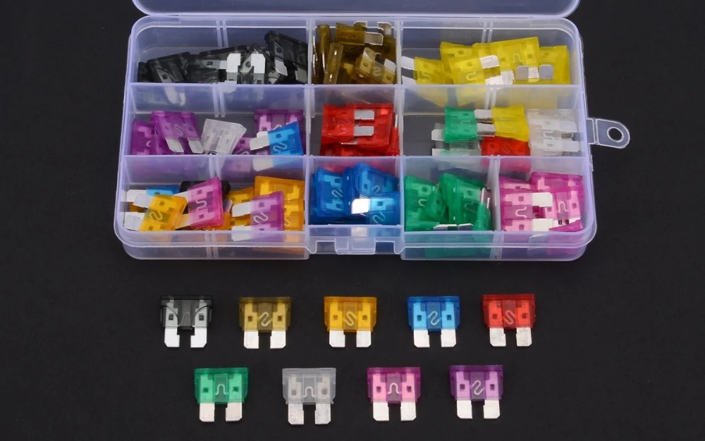
ATO fuses
Once you have fuse holders you will need some fuses. Input and output fuses should be calculated with the load that is behind them! Don’t use 2x25A fuse for the input and 10x 10A fuse for the output channels because the board can handle it. The proper way to fuse is by adding slightly on top of the load for that channel. As an example, if you have 2 meters of 28.8w/m 24v strip, that strip that can use a maximum of 2.4Amps my advice would be to use a 3A or 5A fuse on that channel. The same goes for the input, start with 2x 10A fuse for instance and if you add more load, change those out for larger fuses later on.
Below I’ve specified a kit with lots of different size fuses to get you started (depending on amount of boards you are going to make, buy 1 or more kits), once you know what you generally need you can buy those in bulk.
- 12x PCB fuse
- 2x main input power fuse (Max 25A each)
- 10x output channel fuse (Max 10A per channel)
![]() 1x 100Pcs ATO standard size fuse assortment kit
1x 100Pcs ATO standard size fuse assortment kit
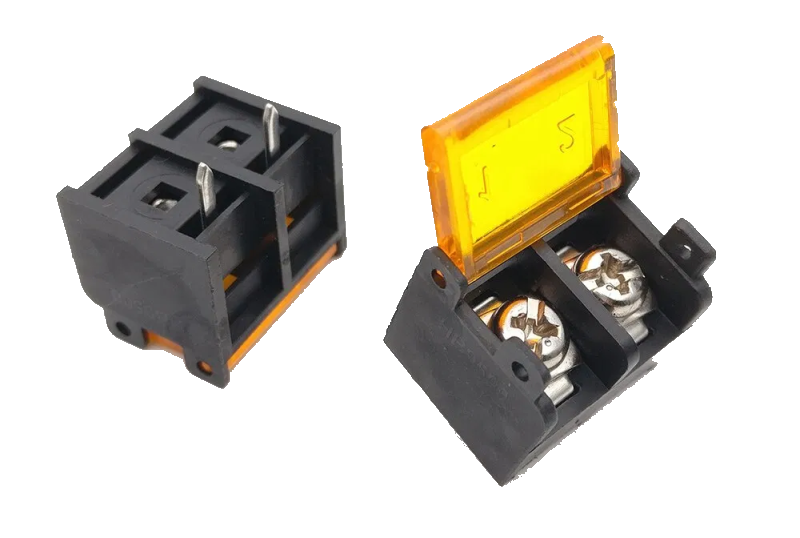
Screw terminals
To secure all the wires to the board you are going to need screw terminals, the QuinLED-Deca-Plus uses especially big one’s to be able to handle lots of current and make wiring thicker cables easier.
- 12x BIG terminals
- 2x Board power input terminal
- 10x Dimming channel output terminals
- 10x Normal terminals
- 10x GPIO terminals
BIG Terminals
![]() 10pcs “HB9500” Screw terminals
10pcs “HB9500” Screw terminals
![]() 100pcs “HB9500” Screw terminals
100pcs “HB9500” Screw terminals
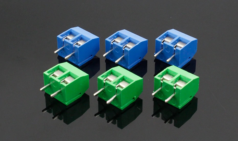
GPIO output channels
For the GPIO output I like to use Blue terminals
![]() 20 Pcs 2 pin BLUE 5.0mm Screw Terminal
20 Pcs 2 pin BLUE 5.0mm Screw Terminal
![]() 100 Pcs 2 pin BLUE 5.0mm Screw Terminal
100 Pcs 2 pin BLUE 5.0mm Screw Terminal
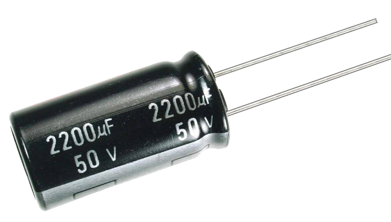
Large Capacitors
To try and stabilize board power, power draw from the power supply and switching noises as much as possible I’ve added a few large capacitors to the design. Although you can use 2x 50v 3300mAh I like using different value capacitors to potentially catch more ripples of different frequencies on the board. If you decide to buy other capacitors then listed below, please make sure to keep the voltage rating the same as specified!
📚 (Board spacing is 18mm, but 16mm variants (mostly 2200uF) also fit without issue)
- 2x 50v 3300mAh Capacitor
50v 3300mAh Capacitor
Additional hardware components, tools and equipment
Above is all the components you need to assemble a complete QuinLED-Deca board! Often it’s best to order components for at least 5 boards, soldering doesn’t always go perfect and once you have one self-built Domotica device, it rarely stays at that number.
Also, don’t forget, this article only lists all the components you need, not the tools and other accessories you might also require. Make sure to take a scroll through this article to see what you might also need so you don’t get frustrated if you don’t have it while building! If you still need LED strip check out this article for high quality (warm) white strips, here for RGB(W) strip. And to power it all, check out this article about power supplies!
p.s. If anything listed on here turns out to be wrong or the link has stopped working, please drop me a line using the contact form so I can correct it!
[ANOTHER FINAL BOARD SHOT, MAYBE INSTALLED]