QuinLED-Dig-Quad Soldering guide
This guide is for the v1 revision 6 board, please see revision history here
To build a QuinLED-Dig-Quad board I have compiled a video guide where we go through all the steps of soldering one together, you can pause at each step and follow along with your own board! Next to that below it is an image guide outlining all components and in what steps I advise to solder them to the board. With both combined and the board being designed in such a way that most people, even new to soldering, should be able to do it!
I know soldering seems daunting at first, but with some decent equipment I think anyone should be able to solder a working board together!
Soldering component highlight guide
Step.1 – Backside – Resistors
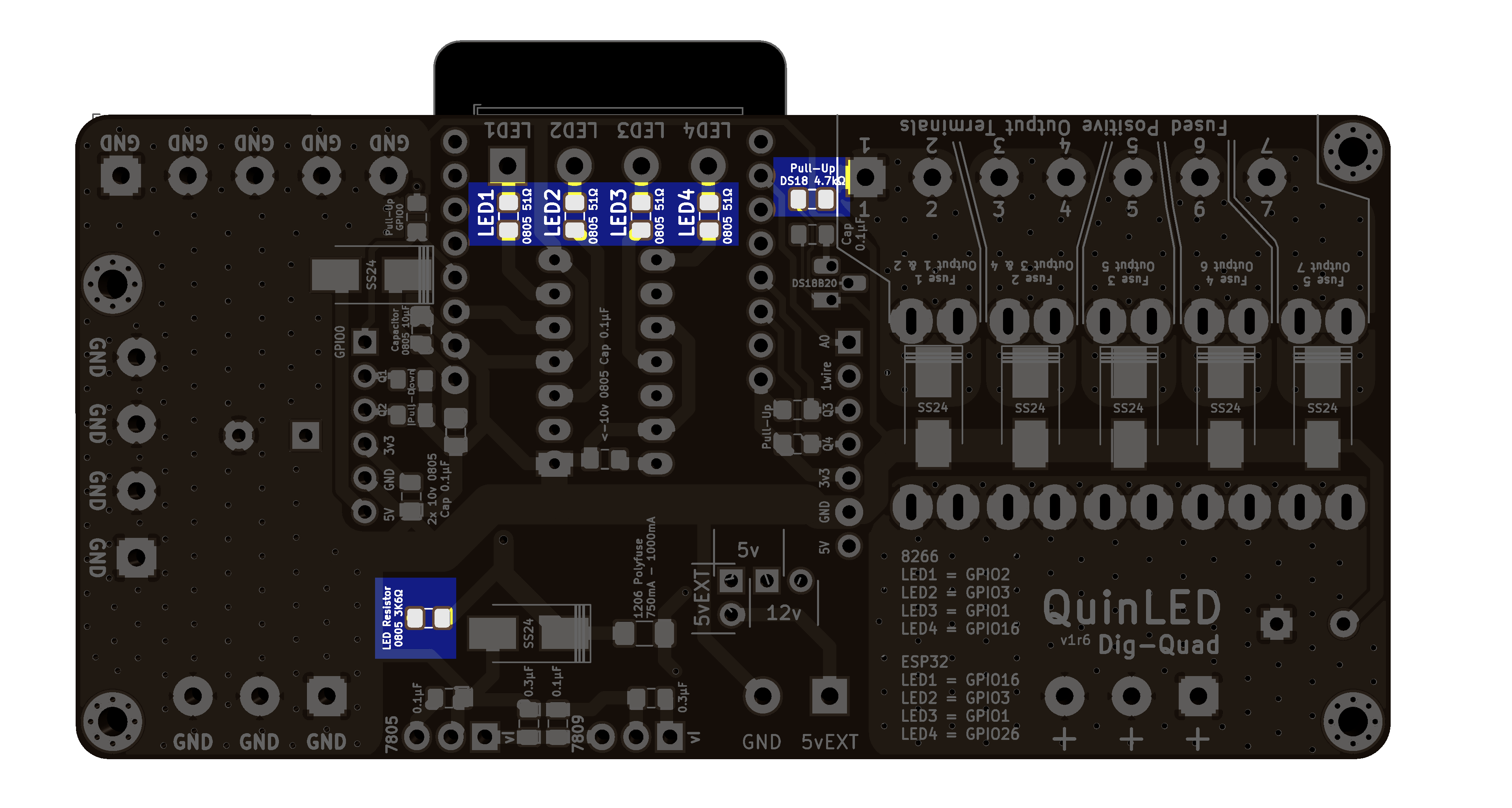 4x 0805 16v 51R
1x 0805 16v 4.7K
1x 0805 16v 3.6K
Step.2 – Backside – Capacitors
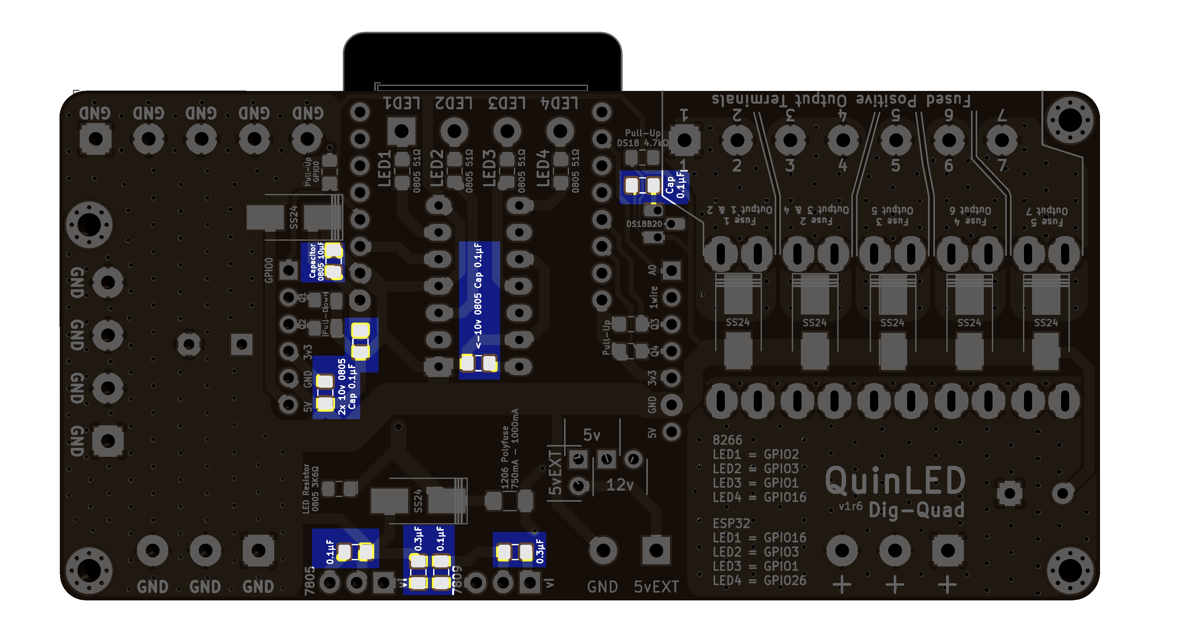
6x 0805 16v 0.1uF (100nF)
2x 0805 16v 0.3uF (330nF)
1x 0805 16 10uF
Step.3 – Backside – Polyfuse
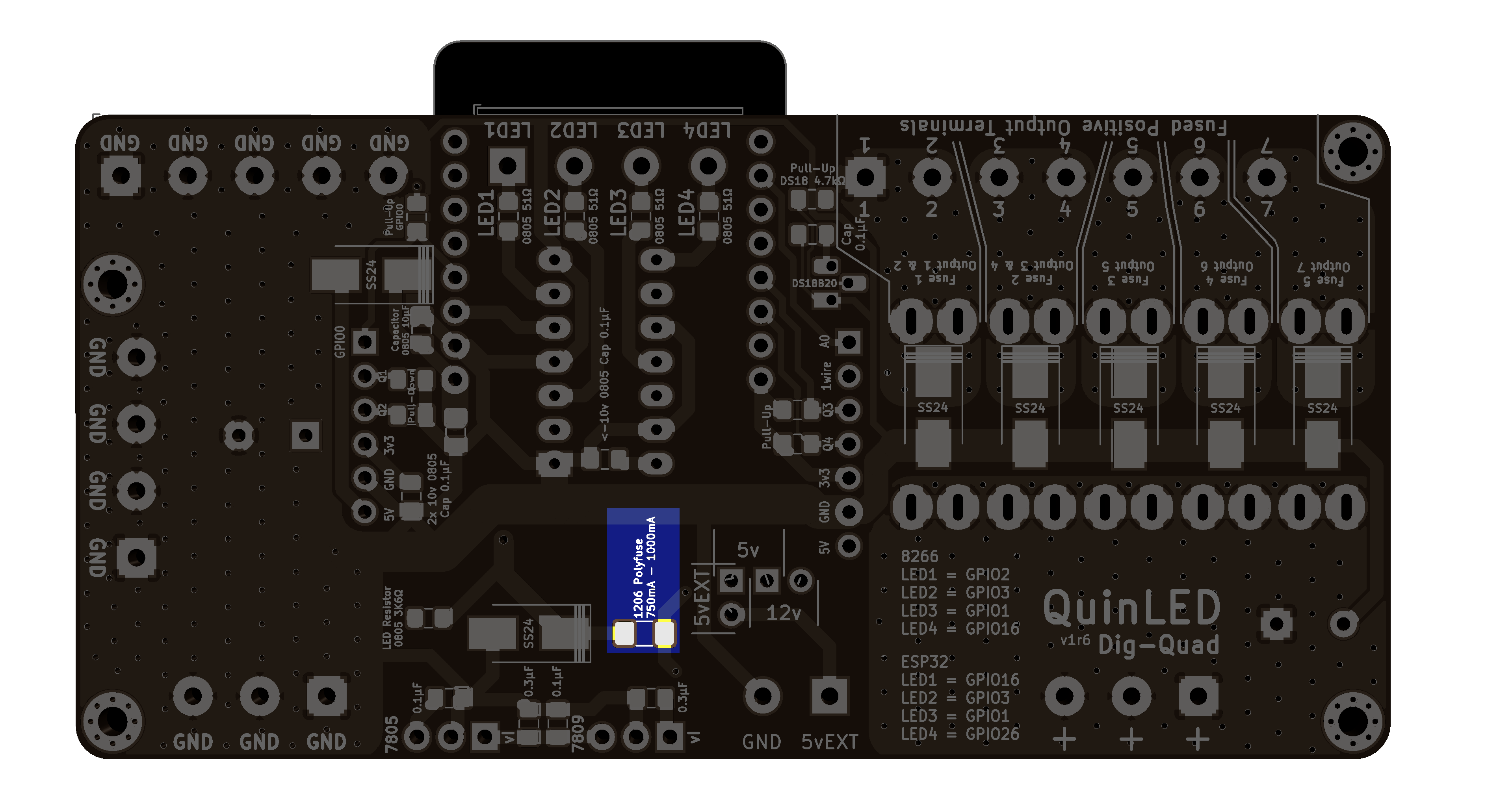 1x 1206 PTC/Poly/SMD fuse 750mA – 1000mA
Step.4 – Backside – Diodes
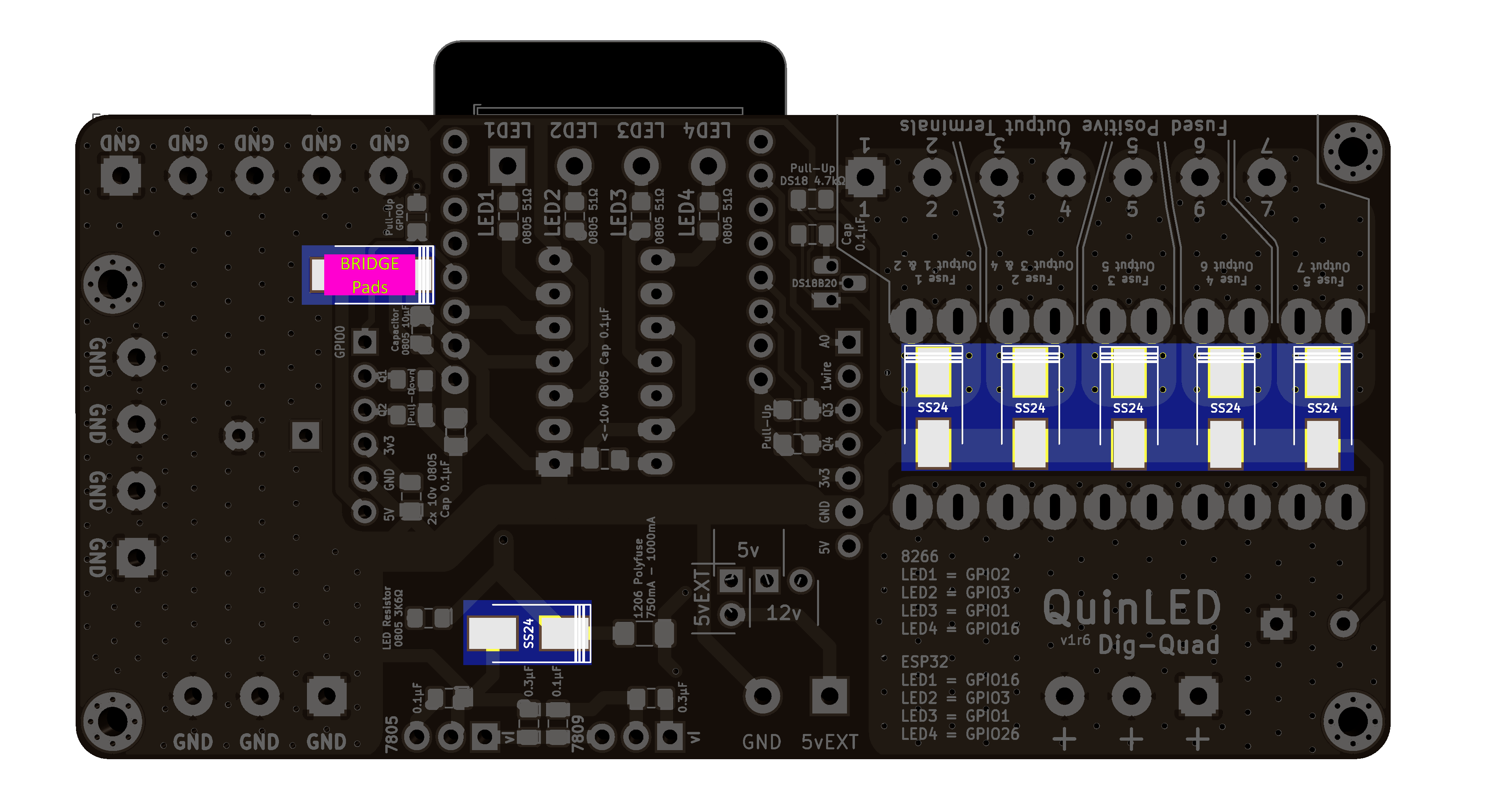
7x SS24 Diode
6x SS24 Diode
(Because of issues with some level-shifters it’s current recommended to bridge the Top SS24 diode fixing the issue)
Step.5 – Frontside – LED
 1x 1206 Blue LED
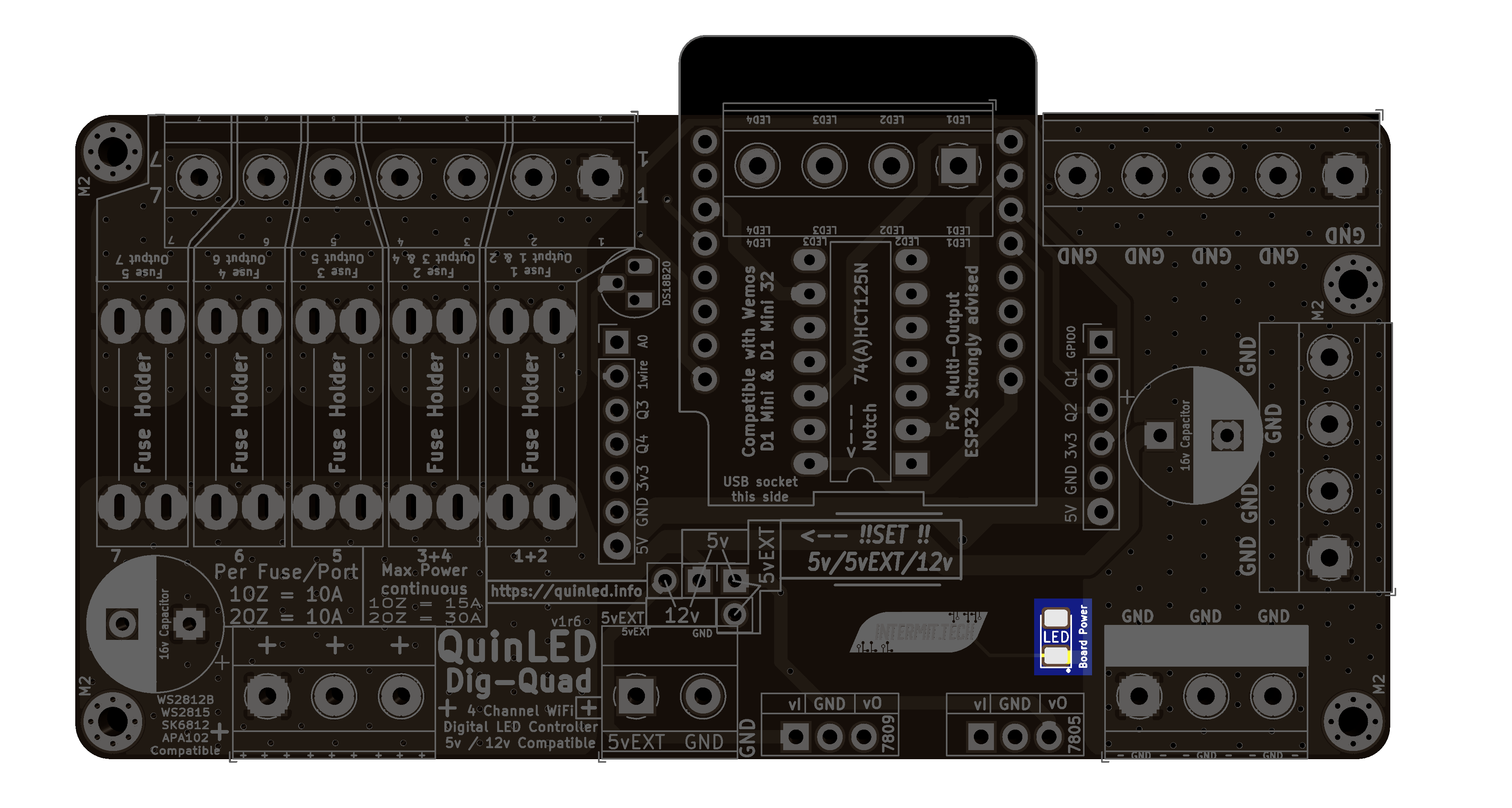
Step.6 – Frontside – Level Shifter
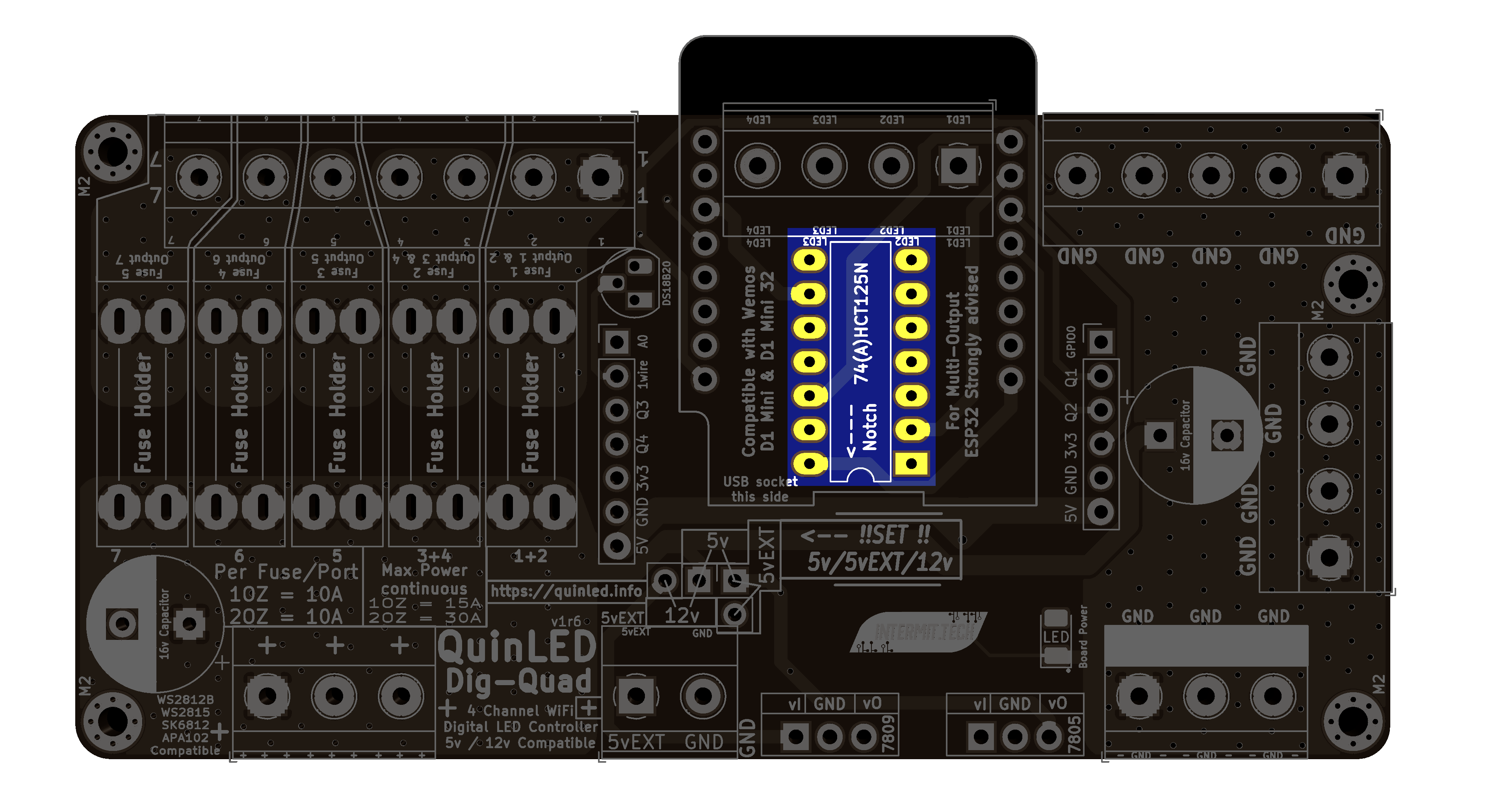 1x 74AHCT125N Level Shifter
Step.7 – Fuse Holders
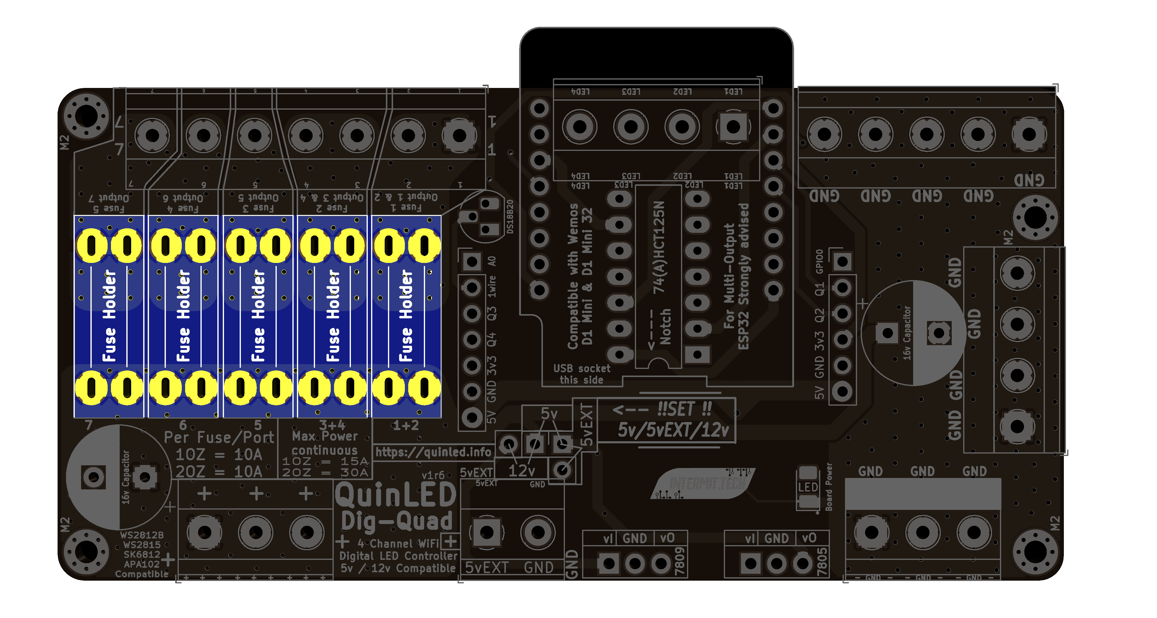
5x Fuse Holder
Step.8 – Pin Headers
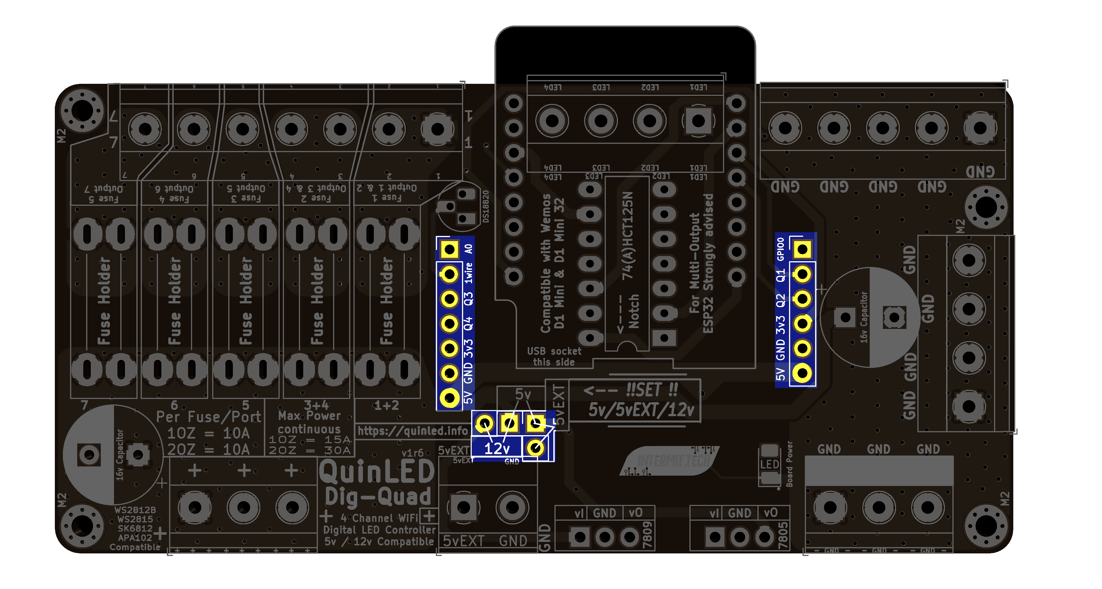
1x 7 pins
1x 6 pins
2x 2pins
Step.9 – Temperature Sensor

1x TO-92 Dallas temperature sensor
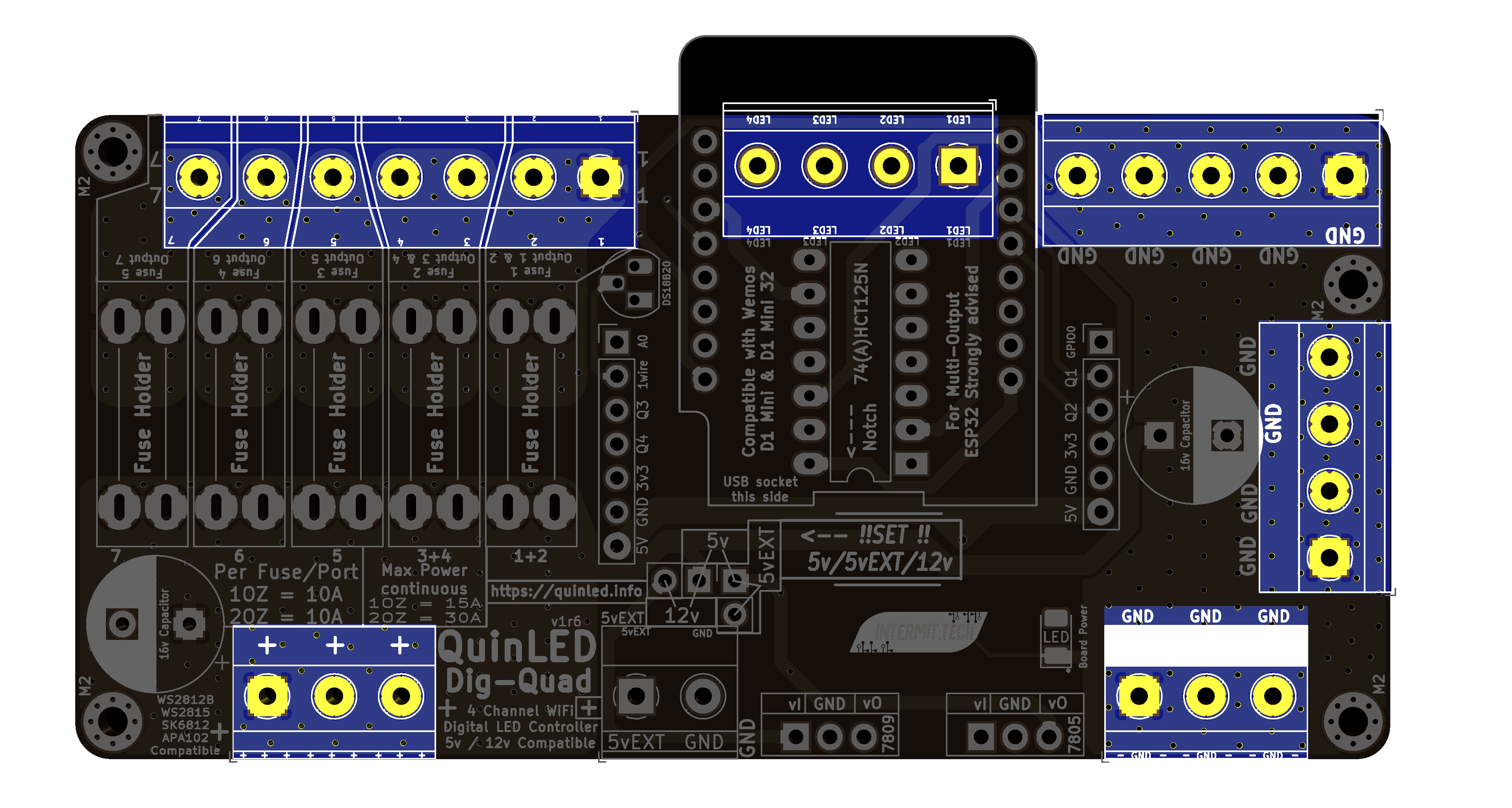
Step.10 – Screw Terminals
Step.Optional – 5vEXT Screw Terminal
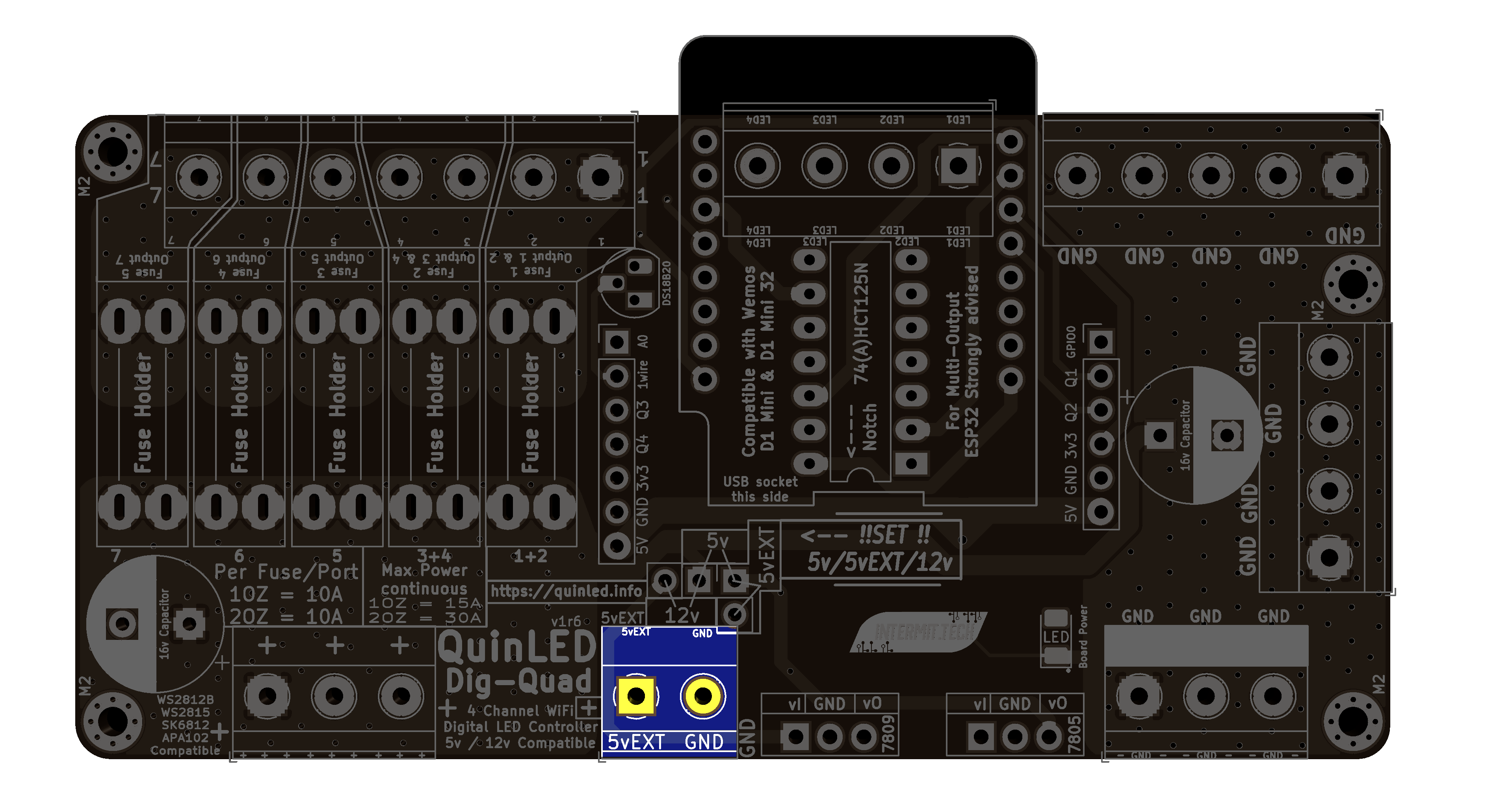
Only needed when feeding board from 2 power supplies, please see dedicated article here
Step.11 – Female Headers + ESP32
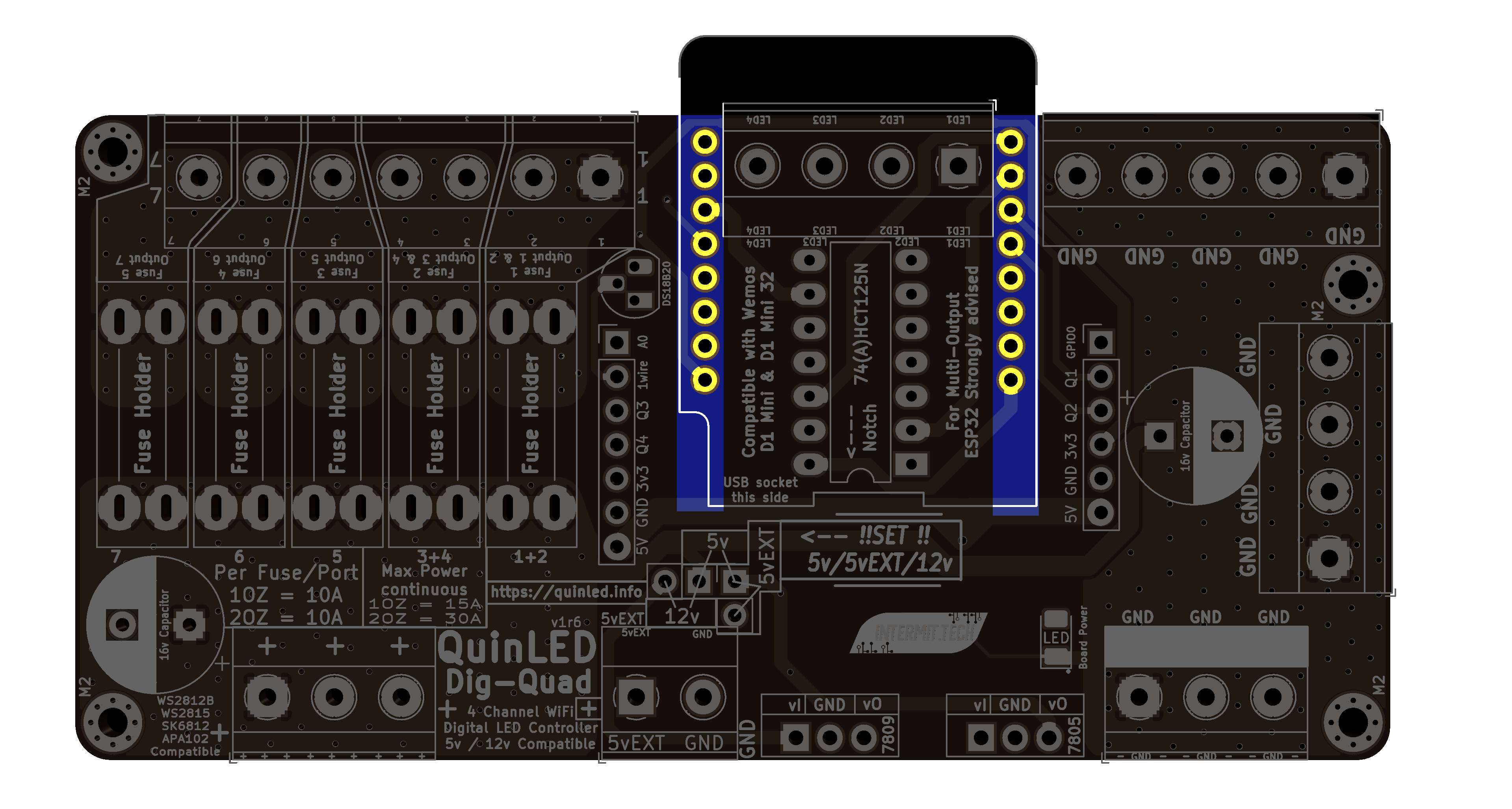 Put in Female Headers, insert male headers into female headers, put ESP32 on top
Solder top of ESP32 first, then solder bottom of the board
Step.12 – Voltage Regulators

1x TO-220 LM7809
1x TO-220 LM7805
Step.13 – Large Capacitors
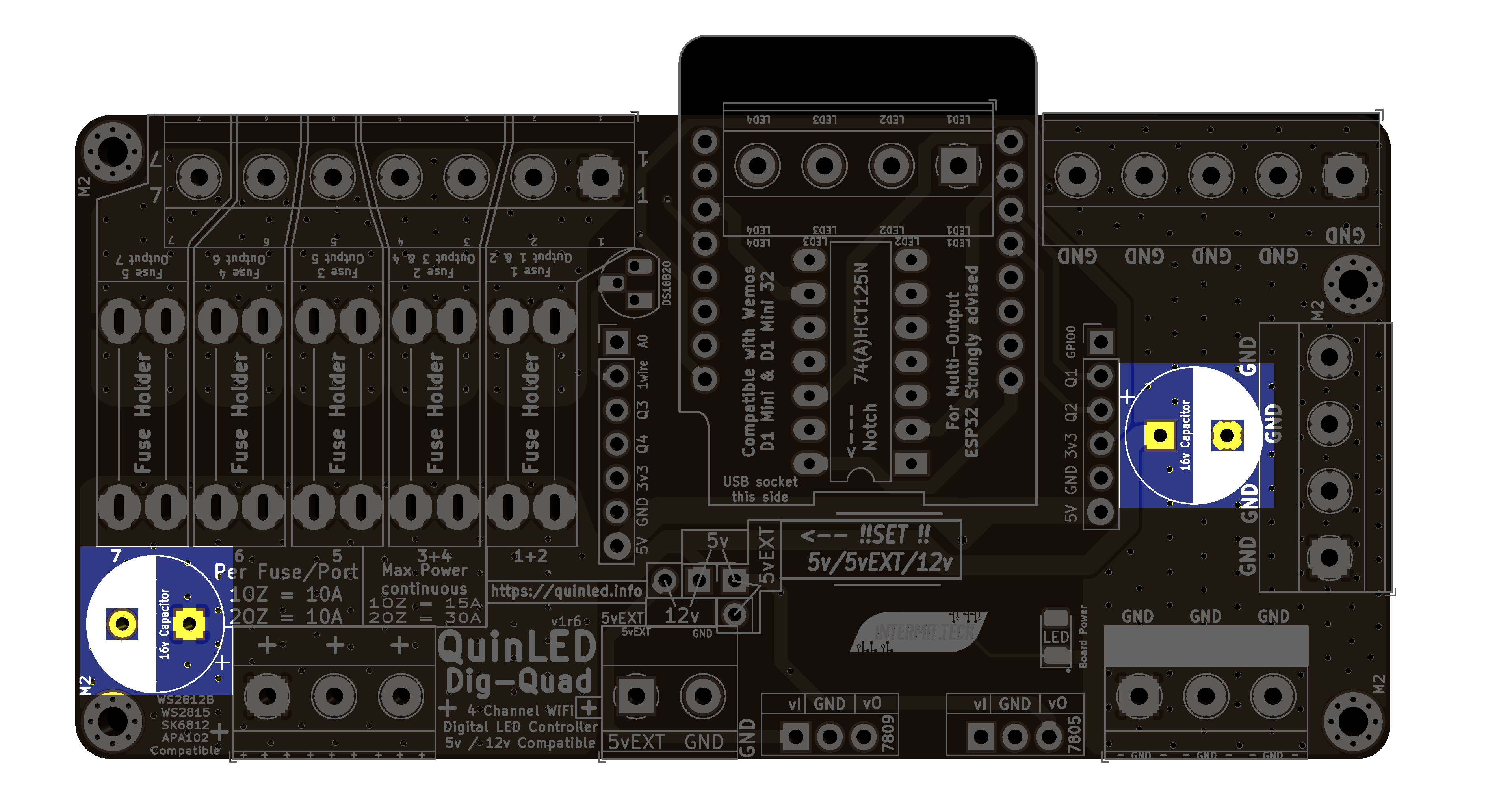
2x 16v 1500uF
Step.14 – Set the voltage jumpers
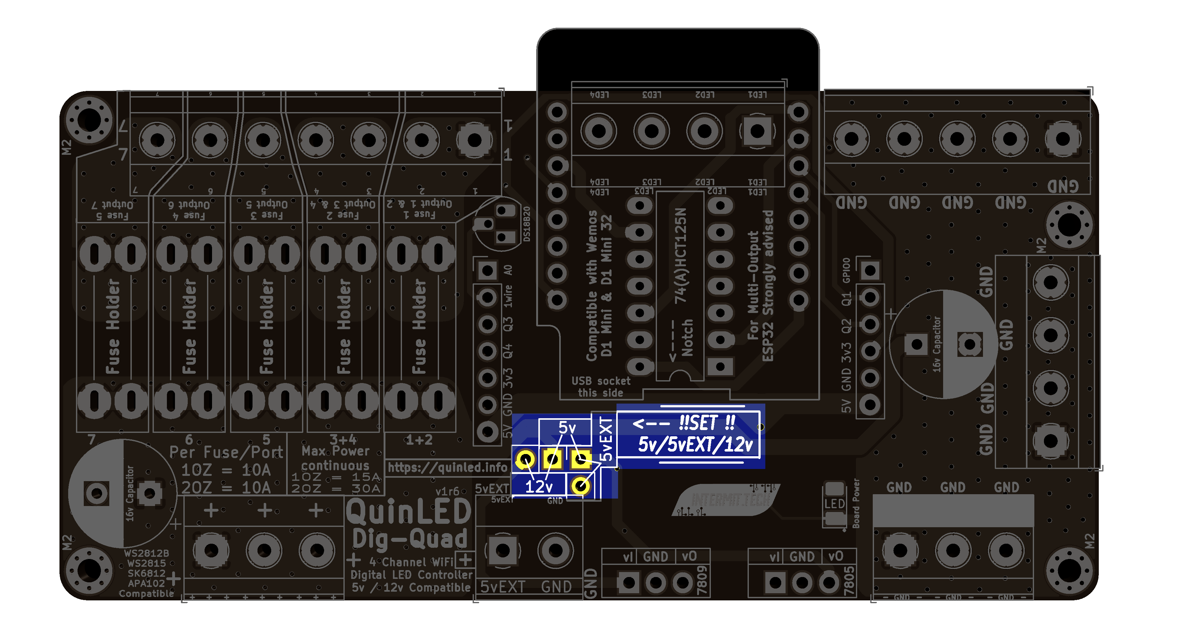 Last step is to set the input power jumper to the correct position!
if 5v LEDs set the Jumper over the 5v pins
if 12v LEDs set the Jumper over the 12v pins
if 5v/12v LEDs with a separate power supply for the LEDs and a 5v power supply for the board, set jumper over 5vEXT pins
Ending remarks
Did all of the above? Great, you’re done, go on to either the wiring guide or one of the programming guides from the front page.